Build yourself a weather station. Part I
June 12, 2020
Intro
I live pretty far away from the office, so my commute can take from 2.5 to 4 hours a day 😱. That includes a lot of time walking. I lost the count of times when I forgot to check if there was rain when going out from home. Or, even worse, the rain came in when I was midway to the train station. As a plus, the Weather app on my iPhone is not very good at making accurate forecasts. It can easily convince me that there is sunny outside when a sneaky rain starts to drop. A couple of months ago I started digging into electronics, microcontrollers, and PCBs, so a side-project idea naturally came up to a surface. I’ll create a simple weather station that will check humidity and temperature outside every morning and notify me if I need to take an umbrella or warm clothes. This is a fun and easy IoT project from the hardware perspective, so I decided to give it a try.
In this series of posts, we will cover how to build an IoT weather station powered up by a web dashboard and Telegram bot. We will start from the birds-eye view first and cover the architecture of what we are going to make.
Table of Contents
- → Build yourself a weather station. Part I
- Building yourself a weather station. Part 2
- Async Unicorns love Rust
- Building a Weather Station Bot
- Building a Weather Station UI
Architecture
This is the general flow of information in the system. In this post, we will go through building each component:
- IoT Device will periodically measure weather information and transfer it to the Backend
- Backend will store all sensor readings in a Weather Database
- Telegram Bot will be used as a notification service that multiple users can subscribe to and receive new weather information
- REST API and Frontend Dashboard are used to present information from the Weather Database in an online dashboard
Choosing the technology stack
The first thing we need to decide before diving into coding is what protocol to use for communication between our IoT device and Backend. I thought that I might want to place stations not only at my home, but also at our country house, so we’ll need to be able to publish messages from several devices to a single endpoint. All messages can be processed asynchronously, and our edge devices do not need to get any kind of response from the backend.
In this situation, the most suitable communication pattern would be some kind of publish-subscribe message passing protocol. In the IoT world, one of the most popular options for this is MQTT. Many devices support it, and there are good and simple to use open-source message brokers such as Eclipse Mosquitto, which we will use in this project.
As for the Backend component, I have decided to use Rust. I could go over all the benefits of this language, but honestly, the primary reason is that I am learning the language and want to have more practice with it 😊.
Hardware setup
First what we will build will be the weather station itself. Despite the popularity of Arduino I have decided to base the project on the ESP32 chip. First, this is a much cheaper option. The development board will cost you less than $4. Second, it packs quite a punch compared to its competitors:
- TCP/IP protocol stack support
- MQTT support
- FreeRTOSFree Real-Time Operating System contains useful implementations of multitasking primitives like asynchronous tasks, queues, and events
- Onboard Bluetooth and WiFi. No need to attach or solder extra modules
- Non-volatile memory storageNVM is like a small hard drive on your chip that allows you to store information when the board is powered off
- 2 core CPU
- Low power consumption and deep-sleep modes that allow to power the chip using rechargeable batteries
- And many more useful things, like mesh-networking that allows you to put many devices into a mesh network that propagates messages between devices without access to the WiFi Access Point
Another important part is the sensor that will measure the temperature. I have decided to use the popular BME280 sensor. It is small, cheap, and accurate. As a bonus, it measures not only temperature but also pressure and humidity 💪🏻.
Bill of materials
To build this project you will need:
-
A ESP32 development board. I used ESP32 WROOM devkit
- BME 280 sensor. I strongly recommend using a breakout board since the sensor itself is very smallIf you will order a Chinese breakout board for the sensor you might need to solder pins to the board. It isn’t hard, but make sure that you have the necessary soldering equipment at hand. If you do not know how to solder, refer to the multitude of guides and videos over the internet. For example, this one . It can use widely supported SPI and I2C protocols for communication with other PCBs
- 3.3V or 5V micro USB power source for the ESP32 board. I use a simple power bank that you regularly use to charge your phoneAnother option is to use a power cell. It is a slightly more complicated setup, which I will cover in another post
- A set of jumping wires to connect the sensor to the devboard
- A computer with a free USB port that you can use for coding and flashing
Wiring everything together
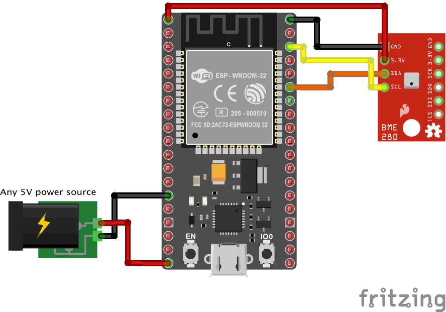
The wiring is not complicated, you will need to connect the BME280 sensor to the board and power it up. You do not have to wire up a power source since the dev board can be powered via micro the USB port. You can simply connect it to your PC, phone charger, or a power bank.
The next part that’s still in the mist is how the sensor communicates with our ESP32 board. Like software that has a TCP/IP or UDP stack for inter-device communication, hardware has a set of commonly used protocols for data transfer. We will use the I2C (Inter-Integrated Circuit) protocol for communications since it means fewer wires and leads to a less complicated setup. I2C is meant for data transfer between multiple devices that are closely placed, which fits our case perfectlyAnother option we have is to use SPI (Serial Peripheral Interface), but it requires more wires, so we will go with the more economic option to save pins on our ESP32 board .
You can see SDA (red) and SCL (yellow) lines that are connected to BME280 on the schematics. Those will be used for communication between our ESP32 board and the sensor.
Next, we will cover how I2C works, which will be important to understand when we will start coding.
A few words on I2C
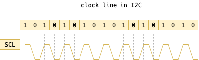
I2C is a synchronous communication protocol that allows multiple devices to exchange information. Synchronous means that all connected devices are synchronized using a common clock. In the case of I2C, the clock is ticking over the SCL wire.
All frames and clock signals are sent in binary format. To achieve this, a set of thresholds is selected. For example, if the voltage on the wire is between 0.4V and 0.8V it is considered 0, and if it is from 2V to 2.7V then it is considered high. All other values are considered to be invalid. Different microcontrollers use different thresholds, so there are a few common sets of thresholds. Concrete values are not important for our purposes as long as you catch the main point.
Let’s expand a bit on what do we mean by saying “clock”. It is actually no more than a periodic pulse of some predetermined frequencyMost I2C devices can communicate at the clock rate of 100kHz or 400kHz . By itself, the clock is not very useful, but combined with the second wire SDA it allows for data transfer between one or more primary devices called masters and multiple secondary devices called slaves. In the idle state, the clock is constantly pulsing, while the SDA line is set to 1 in the idle state.
In I2C the information is exchanged in blocks called frames. Each frame contains 8 bits of information and an additional ACK/NACK bit that is used for confirmation from the slave device. After the first 8 bits of the frame is sent, the slave device is given control over SDA. To acknowledge that the frame was received, the device must pull the SDA line low before the 9th clock pulse. If it did not do this, then the master device can deduce that something bad had happened and decide how to proceed.
The master device is the one to start the communication. In I2C, masters can send 2 types of messages also called frames: address frame and data frame. The address frame is used to select a slave device that should receive the data, which comes in the next one or several frames.
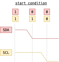
First, we need to indicate that data transfer is about to happen. A special start condition is used for this purpose: the master device must set SCL to 1 and pull SDA to 0 after thatNote that master always oscillates SCL at a constant rate. So the start condition might be seen as waiting when the clock is hight and then setting the SDA line to . This action notifies all slave devices that the data transmission is about to begin.
The next frame is always the address frame. Each device address in I2C is 7 bits long0000001, 0000010, 0000011 and so on . The address frame contains those 1 bits which are read by slave devices each time the clock goes high. Those 7 bits are then followed by a single read/write bit which indicates if the following data frames will read or write information.

The following one or more frames are data frames, which also contain 8 bis of information followed by ACK/NACKACKnowledged/Not ACKnowledged bit. Each bit is set by the master before the clock transitions from 0 to 1. While the clock is 1, the slave device can read the incoming bit. The data will be received by the addressed slave device until a stop condition is met: the master device pulls the SDA from 0 to 1 right after the SCL transitioned from 0 to 1.

To Be Continued
At this point, we have outlined out architecture and tech stack, chose and wired up the hardware and got into how integrated circuits can communicate between each other using two wires and I2C protocol.
In the next post we will harness the power of ESP32 by writing firmware which will collect data from BME280 and send it to our MQTT server via a wireless network. Subscribe to the RSS feed to get notified when the next post comes out.
Next post in the series: Coding For ESP32